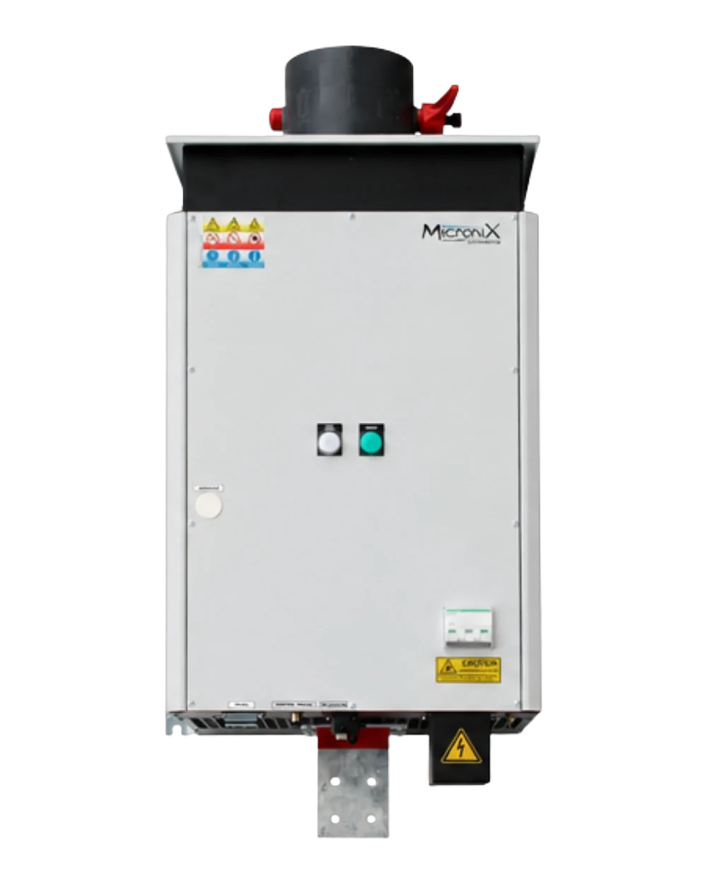
Compact, configurable wall-mounted rectifiers with improved efficiency. Filtered-air cooling, operation up to 40 °C (50 °C on request), shock and corrosion resistant. High-quality DC output: 0–100 % voltage and current regulation, accuracy and stability < 0.5 %, ripple < 2 %, efficiency up to 94 %.
The Microswitch range comes in several ratings; the figures below are those of the MGT4. Each unit is sized to your application by our engineering department.
| Voltage | Available current ratings (A) |
|---|---|
| 8 V | 750 · 1000 · 1250 |
| 10 V | 750 · 1000 · 1250 |
| 12 V | 750 · 1000 · 1250 |
| 16 V | 750 · 1000 · 1250 |
| 20 V | 750 · 1000 |
| 25 V | 650 · 750 |
| 30 V | 500 · 650 |
| 40 V | 400 · 500 |
| 50 V | 300 · 400 |
| 60 V | 250 · 300 |
| 80 V | 200 · 250 |
| 100 V | 150 · 200 |
Voltage ratings above 100 Vdc: on request.
Configure this product to match your process: control, metering and specific options. Three families of options, which can be combined to suit your application.
Reverses the direction of the current in the circuit — a real asset when starting up your bath.
Optimal accuracy across two orders of magnitude, to cope with varying currents.
Regulation measured at the load terminals: compensates for the voltage drop in the power cables.
Voltage or current ramp-up, plus a cycle timer for controlled start-ups.
Dual-output rectifier: balanced current sharing from a single setpoint, with simplified wiring.
A rectifier does not treat the parts: it supplies the regulated direct current your line needs. Here are the processes powered by the MGT4 on our customers' sites.
Anti-corrosion zinc deposit on steel parts, in a tank or in a barrel.
See the page →Nickel deposit for wear resistance, dimensional build-up and finishing.
See the page →Thick chrome layers on parts subject to friction.
See the page →Controlled oxidation of aluminium to protect and colour it.
See the page →Immersion coating under current, for even coverage.
See the page →Gold, silver, palladium, rhodium: thin deposits where every micron counts.
See the page →The rectifier powers the bench and follows the test profiles of your equipment.
See the page →The 8 surface finishing processes covered by Micronics rectifiers.
See the overview →Worth remembering: the treatment itself takes place on your line, with your baths and your processes. Micronics designs, supplies and maintains the rectifier that powers it — and that is what determines how consistent the deposit is.
Four steps between your workshop mains supply and your installation.
Your installation is fed by the mains network, in alternating current. A treatment bath, however, needs direct current.
The rectifier turns that alternating current into direct current, the only form your application can use.
You set a voltage or current setpoint. The electronics hold it continuously, despite variations in the load and in the mains supply.
The regulated direct current goes out to your equipment. Continuous measurement compares the result with the setpoint and corrects any deviation immediately.
A rectifier is rarely bought off the shelf: it is selected, configured, installed and maintained.
Process, voltage, current, environment, installation constraints: the right rectifier is chosen from your actual requirement.
Describe my requirement →02Control, metering, interfaces: your rectifier is configured for your installation, then assembled in our workshops in Villette-d'Anthon.
See the options →03Our technicians come on site for the connection, the settings and the handover to your teams.
On-site service →04Servicing, repair, genuine parts: your equipment stays operational year after year.
Repair & maintenance →Our teams design solutions to match your power and environmental constraints.